In our earlier post, I discussed reading joystick input in a ROS node. Now, I’m interested in learning how to utilize the joystick values to control the motors.
Hardware
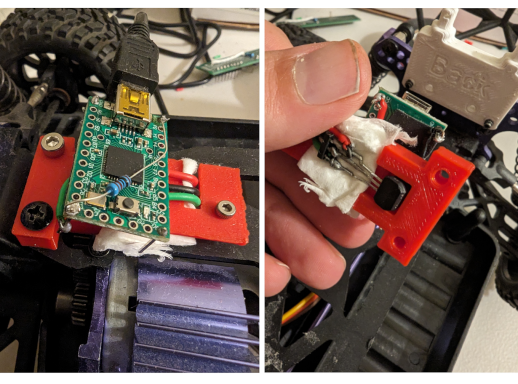
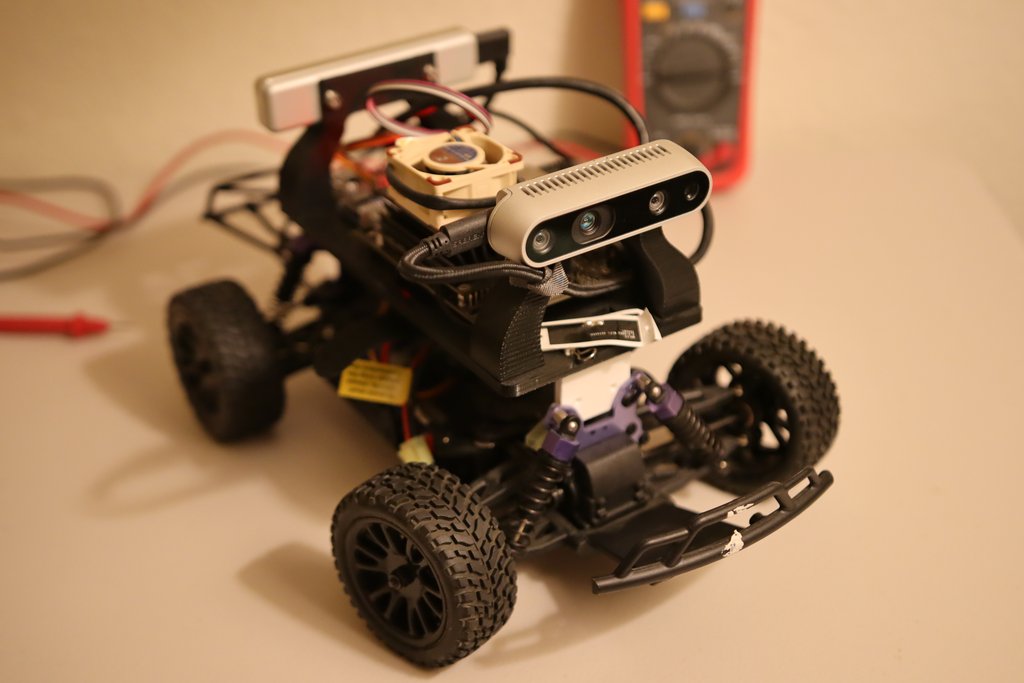
There are two types of motors on board: a servo for steering and a DC motor for throttle control. Both are connected to an Electric Speed Controller (ESC) that originated from the RC Car. The ESC reads input PWM signals and drives the motors. Specifically, the ESC anticipates a signal that is 1 to 2 milliseconds high, with the remainder being low. A high signal of 1 millisecond for steering spins the steering to the maximum left, and a high signal of 2 milliseconds spins the steering to the maximum right. A high signal of 1.5 milliseconds is considered as idle or straight. For throttle control, a high signal of 1 millisecond represents full power backward, 2 milliseconds represents full power forward, and 1.5 milliseconds represents idle or no power.
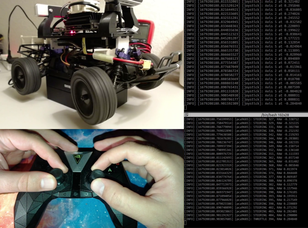
To generate the PWM signals, we utilize the PCA9685 chip, which is linked to the Jetson Nano through an I2C bus. First, we must learn how to handle I2C on the Jetson Nano, then determine what to write to the PCA9685 chip, and lastly, connect the joystick commands to the actuation process, as depicted in the gif above.
I2C in Linux
First, we can use I2C-tools to do some experiments. I2C-tools is a collection of command-line tools for interacting with I2C (Inter-Integrated Circuit) devices on Linux-based systems. These tools can be used to discover and interact with I2C devices connected to the system, as well as to perform various operations on the devices, such as reading and writing data.
One of the most common applications of I2C-tools is in debugging I2C devices on Linux systems. The tools can be used to scan the I2C bus to detect all connected devices and their addresses and to read and write data to specific registers on the devices. This can be useful for troubleshooting communication issues, detecting conflicts between devices, and verifying the functionality of I2C devices.
Another application of I2C-tools is in developing custom applications that interact with I2C devices on Linux systems. By using the command-line tools, developers can test and validate their code without the need for a dedicated hardware interface. This can save time and reduce the cost of development, as well as make it easier to test I2C devices on different platforms and configurations.
Running PCA9685
To verify that the PCA9685 is properly connected to the Jetson Nano, we can use i2cdetect which is part of I2C-tools. This tool scans all the addresses on the bus and checks if the address is being used. By running the following command, we can confirm that i2cdetect has detected the address 0x40, which is the address of the PCA9685 chip. According to the Adafruit documentation for this chip and board, the address should be set to 0x40.
dev@DonkeyJet: $ i2cdetect -r -y 1
     0  1  2  3  4  5  6  7  8  9  a  b  c  d  e  f
00:          -- -- -- -- -- -- -- -- -- -- -- -- --
10: -- -- -- -- -- -- -- -- -- -- -- -- -- -- -- --
20: -- -- -- -- -- -- -- -- -- -- -- -- -- -- -- --
30: -- -- -- -- -- -- -- -- -- -- -- -- -- -- -- --
40: 40 -- -- -- -- -- -- -- -- -- -- -- -- -- -- --
50: -- -- -- -- -- -- -- -- -- -- -- -- -- -- -- --
60: -- -- -- -- -- -- -- -- -- -- -- -- -- -- -- --
70: 70 -- -- -- -- -- -- --
We would like to create a PWM signal with 1 to 2 milliseconds of high time and a frequency of 60Hz. At 60Hz, 1 millisecond would be equivalent to the duty cycle of 0.001 / (1.0/60) = 0.06 or 6 percent. And 2 milliseconds would be equivalent to the duty cycle of 16 percent.
For that, it is necessary to have a look at the datasheet of the chip here. There are a lot of registers in the datasheet. The main ones to understand are Mode registers 1 and 2. According to the datasheet to generate such a signal we need to:
- Reset the chip by writing
0x10to Mode Register 1 at the address0x00. - Wait a few moments.
- write the correct prescale to prescale register at the address
0xFE. The prescale can be calculated fromrefresh_rate = (clock frequency)/(4096 x (prescale + 1)). The clock frequency is 25MHz and the desired refresh rate is 60 Hz so we need to write 101 in decimal or0x65to prescale register. - Write
0xA0to mode register 1. - 1 to 2 milliseconds of high time of signal would be equivalent to about 246 – 492 for PWM registers with a neutral position at 367. These registers are at addresses
0x06,0x07,0x08and0x09for channel zero (throttle) and0x0A,0x0B,0x0Cand0x0Dfor channel 1 (steering).
We can use i2cset in terminal (again part of I2C-tools) to write to the PCA9685 chip and actuate the motors. To set restart and set the frequency to 60Hz we need to run:
dev@DonkeyJet:~$ i2cset -y 1 0x40 0x00 0x00
dev@DonkeyJet:~$ i2cset -y 1 0x40 0xFE 0x65
dev@DonkeyJet:~$ i2cset -y 1 0x40 0x00 0xA0
Now to turn the steering to one side we can run
dev@DonkeyJet: $ i2cset -y 1 0x40 0x0A 0x00 && \
>   i2cset -y 1 0x40 0x0B 0x00 && \
>   i2cset -y 1 0x40 0x0C 0xFA && \
>   i2cset -y 1 0x40 0x0D 0x00
ROS Node
You can find the complete ROS node on the GitHub of the project here. The code has the structure of a standard C++ ROS node.
It uses i2c-dev.h from Linux to communicate with the I2C device. i2c-dev.h provides a file-like interface to write and read from the I2C device. So we can use open, read, write and close functions.
The code starts with initializing the hardware by opening /dev/i2c-1 file which represents the I2C hardware on Jetson Nano. Then we set the address of the PCA9685 as a slave that we would like to communicate with from Jetson Nano. Then we set the frequency of PWM to 60Hz similar to how we did from the terminal but this time from the C++ code. Then we set all the PWM channels to 0% duty cycle.
The ROS node subscribes to /joy topic and it receives the messages that are produced by the joy node that we discussed in previous blog post. It reads axes 1 and 2 of the joystick for throttle and steering, respectively and sends the corresponding values to the PCA9685 via the I2C bus. The video below shows how it works.
To run the same demo from the repository we need to run the following commands. Remember that we are using a docker image called ros_base that we built and pushed to our docker registry in previous posts.
JETSON_IP=<YOUR JETSON IP>
docker -H $JETSON_IP pull ${REGISTRY}/ros_base:latest \
  && docker -H $JETSON_IP buildx build \
    -f Dockerfile.ros2_ws \
    --build-arg BASE_IMAGE=${REGISTRY}/ros_base:latest \
    -t ${REGISTRY}/ros2_ws:latest . \
  && docker -H $JETSON_IP run \
    --name ros2_ws --rm -it --runtime nvidia \
    --network host --gpus all --privileged \
    -e DISPLAY -v /dev:/dev -v /proc:/proc -v /sys:/sys \
    ${REGISTRY}/ros2_ws:latest \
    bash -ic "ros2 run bot_hardware joy"


# In another terminal
JETSON_IP=<YOUR JETSON IP>
docker -H $JETSON_IP exec \
  -it ros2_ws /bin/bash -ic \
  "ros2 run bot_hardware pca9685"
I hope this is useful. Please ask any questions in the comment section below. Thanks.