I came across a discussion on the DonkeyCar discord server about Hall effect sensors that can measure speed using Hall effect sensors and gears. Intrigued, I decided to do some research and came across an IC that seemed suitable for the task, utilizing a similar concept. I was specifically looking for a method to measure speed while considering the following constraints:
The gear on the DonkeyCar is not magnetic, so the chip should be able to detect speed using non-magnetic, but ferrous target gears.
It should be compatible with low voltages since I have both 5V and 3.3V on board.
Additionally, I needed a small and easily mountable solution.
I came across the ATS668LSMTN-T IC on DigiKey. As of the time of writing this blog, the price of the IC has been slightly reduced to $3.28 per item. You can find it for purchase at this link.
Prototype
The ATS668LSMTN-T IC contains a magnet internally. When this IC is positioned in front of a rotating ferrous gear, it can detect the teeth of the gear and generate a square signal. Each rising and falling edge of the signal corresponds to a tooth and valley pair on the gear. By knowing the number of teeth on the gear, we can determine the amount of rotation and calculate the rotational speed by measuring the time.
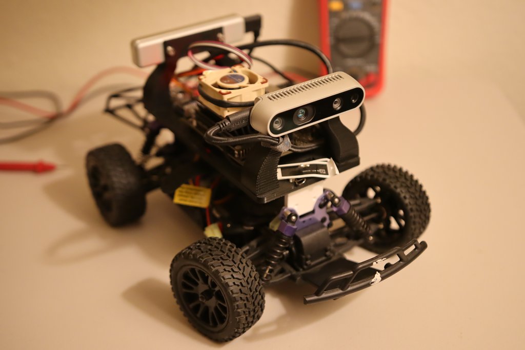
In the accompanying image, I have removed the cover from the top of the gear, revealing the optimal location to mount the sensor. This placement allows for the measurement of the speed of the main shaft, prior to the differential gearbox.
I conducted a test by simply taping the sensor onto the slot and observed the output signal. Fortunately, I was able to obtain a satisfactory PWM signal. However, it is important to note that the sensor requires a 1KΩ pull-up resistor connected to the output. Without this resistor, the sensor does not generate any output.
Adjust camera position with the right mouse button.
Double-click to enter the fullscreen mode.
On mobile devices swipe to rotate.
On mobile devices pinch two fingers together or apart to adjust zoom.
On mobile devices 3 finger horizontal swipe performs panning.
On mobile devices 3 finger horizontal swipe performs panning.
In the next step, I designed and 3D printed a mount, which can be downloaded from here. This allowed for a more secure and stable attachment compared to using tape alone. To affix the sensor body to the 3D printed mount, I utilized double-sided tape.
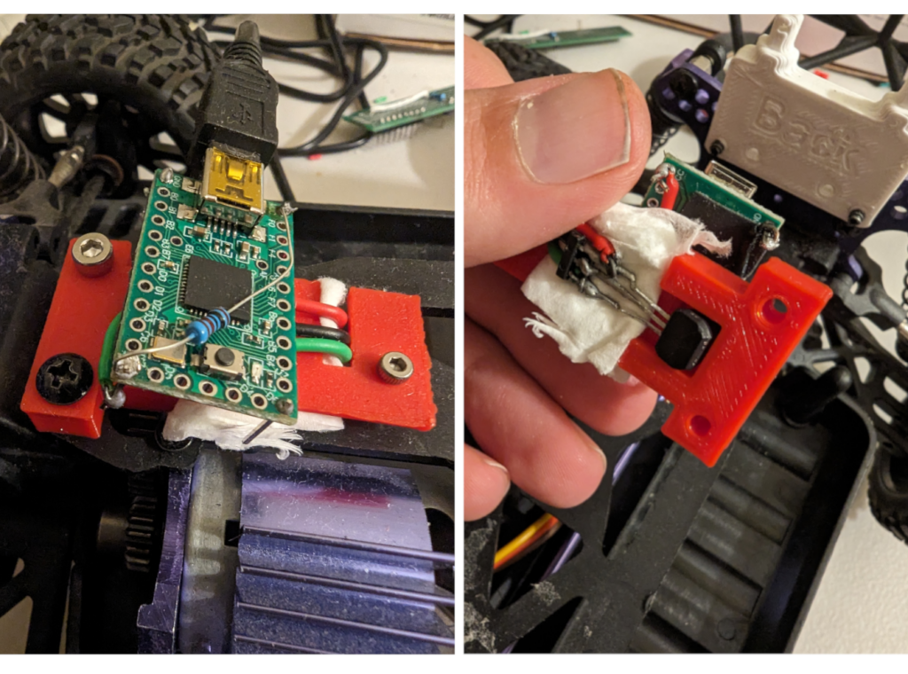
For reading the signal, I employed a Teensy 2.0. It’s important to note that only the Teensy 2.0 version in this particular size has 5V tolerant pins. Other versions of the Teensy in the same size are only 3.3V tolerant. Since our sensor IC requires a voltage of 4V and above, as specified in the datasheet, it’s crucial to use the appropriate Teensy version.
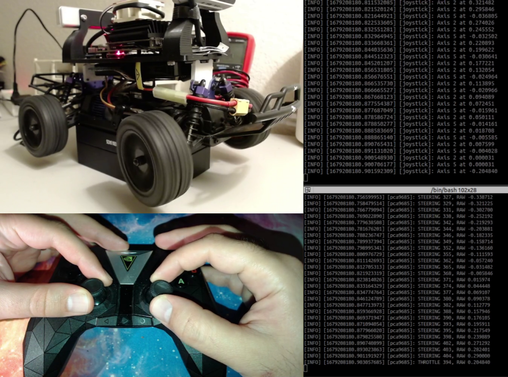
Here are a video of speed readings on the teensy and some more images.
PCB as Improved Mount
It is crucial to address the current mounting setup, which involves using a piece of tissue to keep the sensor in its proper position, as depicted in the images above. To resolve this issue, I have designed a PCB that allows for mounting the Sensor IC on both sides of the PCB, to be able to mount the sensor at correct distance from the gear. Ultimately, I opted to solder the sensor to the back of the PCB, as illustrated in the images. Furthermore, I had to trim the surplus pins on the back of the PCB after soldering to ensure a flat placement on the car’s chassis.
I designed the PCB using KiCad. All the files can be found on the GitHub repository here [Greber Files].
There is still one minor issue that the measurements are very sensitive to the distance between the sensor and the gear. If the distance is too much or too close, the measurement would be very noisy where there is mechanical vibrations. Because the sensor is only attached to the PCB via the pins, you could slightly bend the pins to move the sensor slightly back and forth to fix the issue. In a correct distance, the measurements are very nice.
Problem: We need to read the square signal and measure the car’s speed. The measurement is on a gear with 50 teeth and the car’s wheel is attached to a ring gear in the differential with 39 teeth according to the manual of the car’s chassis. It can be easily proved that the speed of the car in meters per second is as follow:
\begin{array}{rcl}
v =& \dfrac{D.\pi}{2.n} \dfrac{n_{\text{rising edges}}}{\Delta t} \\ \\
v :& \text{Speed of vehicle in meters per second} \\
D :& \text{Diameter of the wheel in meters} \\
n :& \text{Number of teeth of ring gear} \\
n_{\text{rising edges}} :& \text{Number of rising edges in } \Delta t \text{ seconds} \\
\Delta t :& \text{The amount of time in seconds}
\end{array}
To measure the speed, we simply need to count the number of rising edges in the incoming signal from the sensor and record the corresponding time. By utilizing the equation mentioned earlier, we can accurately calculate the speed. In order to accomplish this, I am utilizing the 16-bit timer on the Teensy 2.0 microcontroller in the Input Capture mode.
In the Input Capture mode, interrupts are triggered on the rising edge of the input signal, and the time of the interrupt is automatically captured in specific registers of the microcontroller unit (MCU). By comparing these captured times with the previous one, we can determine the precise amount of time that has passed between each rising edge or tooth of the gear passing in front of the sensor.
Furthermore, to ensure that the speed information is available every 10 milliseconds, or 100 times per second, I have configured the Timer Compare mode to generate an interrupt every 10 milliseconds. This allows us to calculate the speed based on the number of rising edges and the accumulated time. Consequently, the time interval (Δt) in the aforementioned equation is approximately 0.01 seconds.
Here you can find the source code of the teensy firmware.
Currently, this code only measures the speed and prints it out via the USB. Hopefully, this would work with Jetson Nano. We will see.